
Monday Kids Accurate C51 Electronic Clock 4 Bits Clock Kit DIY Electronic DIY Kit LED Display Electronic Modules DIY Electronic Modules
$3.52
Availability:
In stock
SKU
EK316
Payment Security

We are PayPal Verified
PayPal is a secure and trusted payment processing service that allows you to shop online. PayPal can be used at mondaykids.com to purchase items by Credit Card (Visa, MasterCard, Discover, and American Express), Debit Card , or E-check (i.e. using your regular Bank Account).
- Brand Name: Monday Kids
- Supply Voltage: 3V-6V
- Condition: New
- Operating Temperature: -20 ~ 60
- Dissipation Power: NONE
- Application: Alarm
- is_customized: Yes
- Type: Timer
- Model Number: C51 Electronic Clock Kit
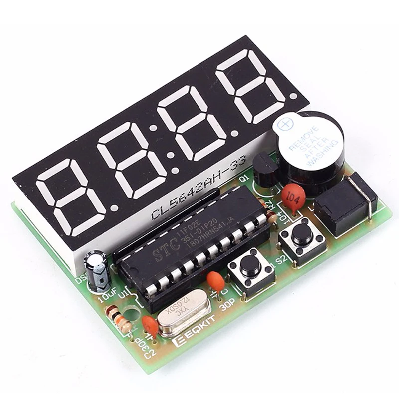
- PCB Size: 52mm * wide 42mm
- Feature: electronic diy kit, electronic modules

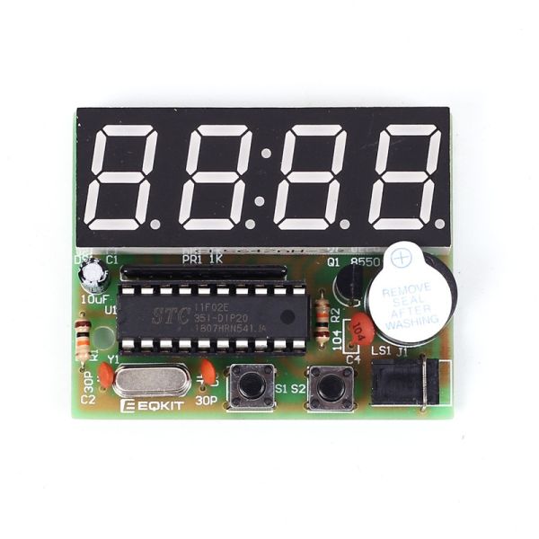
AT89C2051-based of four electronic clock kit
Kit Model: YSZ-4
Supply voltage: 3V-6V
PCB Size: 52mm * wide 42mm
Function :
1. Seconds correction (for precise School)
2. Switch to every minute independent display interface
3. whole point of time (8-20 o'clock chime can be turned off)
4. Two alarm settings (you can turn off the alarm function)
Kit Features:
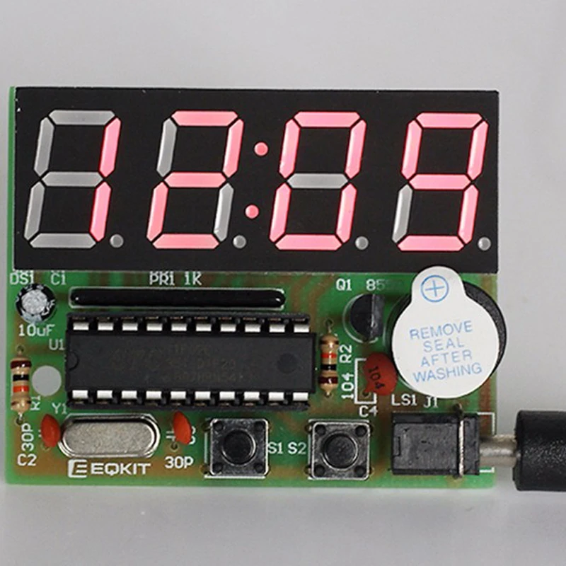
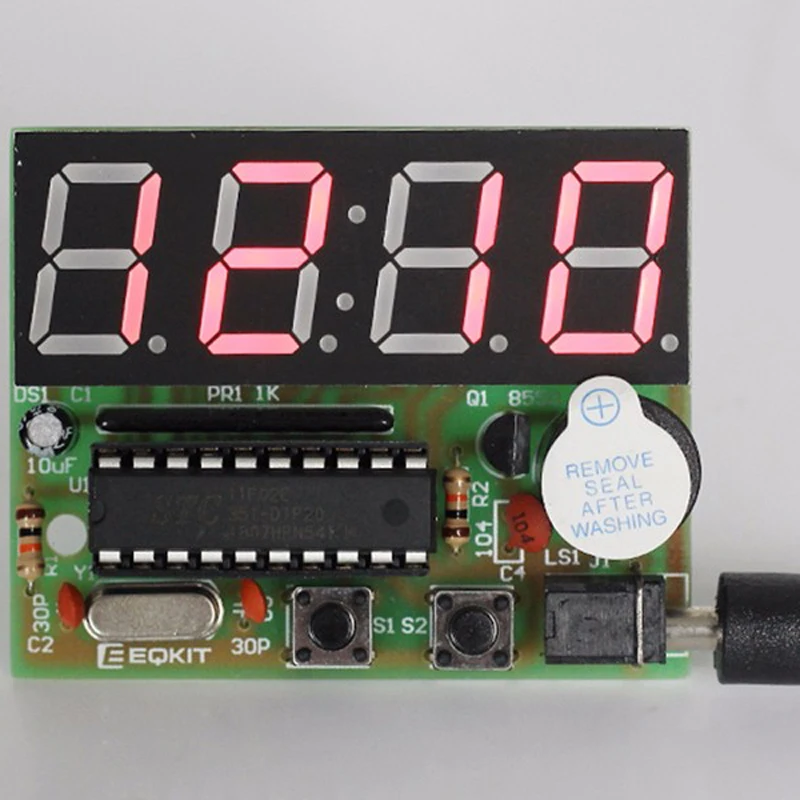
A. 0.56 inch special red digital clock for display;
B. Import AT89C2051 for master chip;
C.1.2mm thick PCB made from military grade FR-4 board;
D. accurate travel time, travel time error range error -1 to +1 seconds every 24 hours.
This kit contains a USB to 3.5mm power cord, plug in the USB charger can be used.
1. Introduction
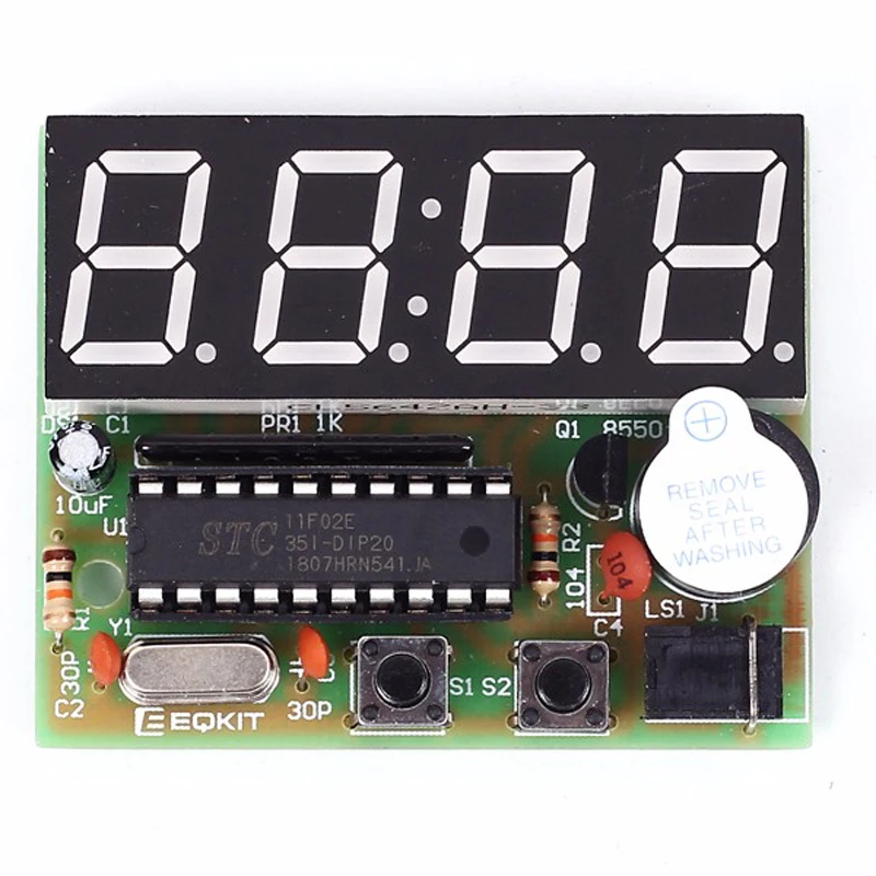
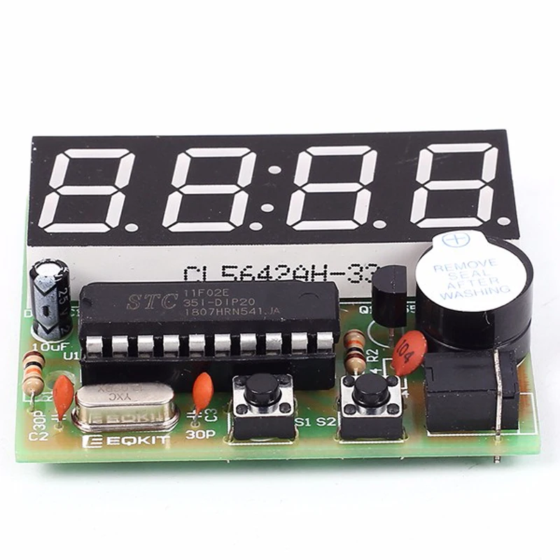
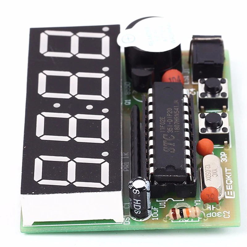
YSZ-4 four electronic clock, it takes AT89C2051 as its core, a total of 16 electronic components to come true the two channels of the alarm clock, (8:00-20:00) on time alarm ,accurate adjustment , and other functions.
2. Parameter
NO. | Parameter | Value |
1 | Operating voltage | DC 3V-6V |
2 | PCB board material | RF-4 |
3 | Size | 52mm*42mm |
3. Principle
The whole system by MCU minimum system, key input circuit, display circuit, buzzer circuit and power supply parts.
1>. MCU minimum system: including the U1 (AT89C2051), C1, R1 for power on reset circuit .Clock circuit is composed of C2, C3 and Y1.
2>. The pressed key input circuit:composed of S1, S2, short press the button once a loud buzzer rang, long press the button once two loud buzzer rang.
3>. The display circuit:4bits common cathode and on PR1 Resisters Packs .
4>. Buzzer circuit:composed of Q1, R2 and LS1, short press the button once a loud buzzer rang, long press the button once two loud buzzer rang.
5>. J1 is 5v power supply input terminal, C4 filtering.
4. Operation instruction
It will display 12:59 when Power-on,while is normal interface("hours:minutes"). The both channels of alarm clock are opened.At the same time,the first alarm clock has been set at 13:01.the second alarm clock has been set at 13:02.
After power on ,short press S2.The display of digital tube will switch between "hours:minutes" and "minutes:seconds";Long press S1 to enter the system Settings menu. there are A, B, C, D, E, F, G, H, I submenu. Short press S1 sub-menu plus increase by degrees.finally back to the normal interface
A Sub menu : Correction for hours
Display data will add 1 after press S2.after adjusted the A Submenu,then short press S2 to save the adjusted results and quit A submenu,enter B sbumenu
B Sub menu : Correction for minutes
Display data will add 1 after press S2.after adjusted the B Submenu,then short press S2 to save the adjusted results and quit B submenu,enter C sbumenu
C Sub menu:on time alarm switch
The default state is ON (on-time-alarm is open from 8:00 to 20:00)
It will switch between ON and OFF(on-time-alarm is closed) when press S2. Short press S2 to save the adjusted results and quit C submenu,enterD sbumenu
D Sub menu:The first alarm-clock switch
The default state is ON (the first alarm-clock is opened)
It will switch between ON and OFF(first-alarm-clock is closed) when press S2.
If set to ON, short press S1 to save and quit,then enter E submenu;
If set to OFF, short press S1 to save and quit ,then enter G submenu;
E Sub menu:The first alarm clock set for hours
Display data will add 1 after press S2.after adjusted the E Submenu,then short press S2 to save the adjusted results and quit E submenu,enter F sbumenu
F Sub menu:The first alarm clock set for minutes
Display data will add 1 after press S2.after adjusted the F Submenu,then short press S2 to save the adjusted results and quit F submenu,enter G sbumenu
G Sub menu:The Second alarm-clock switch
The default state is ON (the second alarm-clock is opened)
It will switch between ON and OFF(second-alarm-clock is closed) when press S2.
If set to ON, short press S1 to save and quit ,then enter H submenu;
If set to OFF, short press S1 to save and quit ,then enter normal interface;
H Sub menu:The second alarm clock set for hours
Display data will add 1 after press S2.after adjusted the F Submenu,then short press S2 to save the adjusted results and quit H submenu,enter I sbumenu
I Sub menu:The second alarm clock set for hours
Display data will add 1 after press S2.after adjusted the I Submenu,then short press S2 to save the adjusted results and quit H submenu, then enter normal interface.
Second correction:
Short press S2 in the normal interface,then enter "minutes : seconds" interface .Long press S2,make the second zero.Then short press S2 twice enter normal interface
5. Schematic
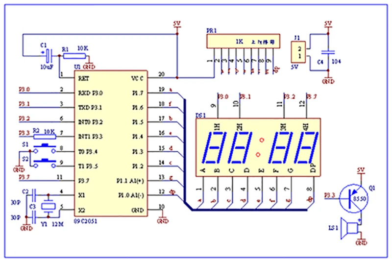
Note: there is direction for PR1 Resisters Packs , there is one side of the word in the direction of the MCU.Pay an attention!!!
6. Component listing
NO. | Component Name | PCB Marker | Parameter | QTY |
1 | Metal Film Resistor | R1,R2 | 10K | 2 |
2 | Ceramic Capacitor | C2,C3 | 30pf | 2 |
3 | Ceramic Capacitor | C4 | 0.1uf 104 | 1 |
4 | Electrolytic Capacitor | C1 | 10uF/25V | 1 |
5 | Network Resistor | PR1 | 1K | 1 |
6 | Crystal Oscillator | Y1 | 12MHz | 1 |
7 | S8550 | Q1 | TO-92 | 1 |
8 | Button | S1,S2 | 6*6*5mm | 2 |
9 | AT89C2051 | U1 | DIP-20 | 1 |
10 | IC Socket | U1 | DIP-20 | 1 |
11 | Active Buzzer | LS1 | 5V | 1 |
12 | Digital Tube | DS1 | 4Bit Red | 1 |
13 | DC Socket | J1 | 3.5mm | 1 |
14 | Power Cable | USB to 3.5mm | 1 |
NOTE :Users can complete the installation by PCB silk screen and component listing

- Unit Type: piece
- Package Weight: 0.048kg (0.11lb.)
- Package Size: 15cm x 12cm x 10cm (5.91in x 4.72in x 3.94in)
Write Your Own Review
Discover More Products from Its Parent Categories: