
Monday Kids DC 5V 35mA ICL7107 Digital Ammeter Red LED Display Module DIY Kit Electronic Learning
$5.27
Availability:
In stock
SKU
EK710
Payment Security

We are PayPal Verified
PayPal is a secure and trusted payment processing service that allows you to shop online. PayPal can be used at mondaykids.com to purchase items by Credit Card (Visa, MasterCard, Discover, and American Express), Debit Card , or E-check (i.e. using your regular Bank Account).
- Brand Name: Monday Kids
- Condition: New
- Type: Logic ICs
- Operating Temperature: -30~85 celsius
- is_customized: Yes
- Model Number: Digital Ammeter
- Application: Digital Ammeter

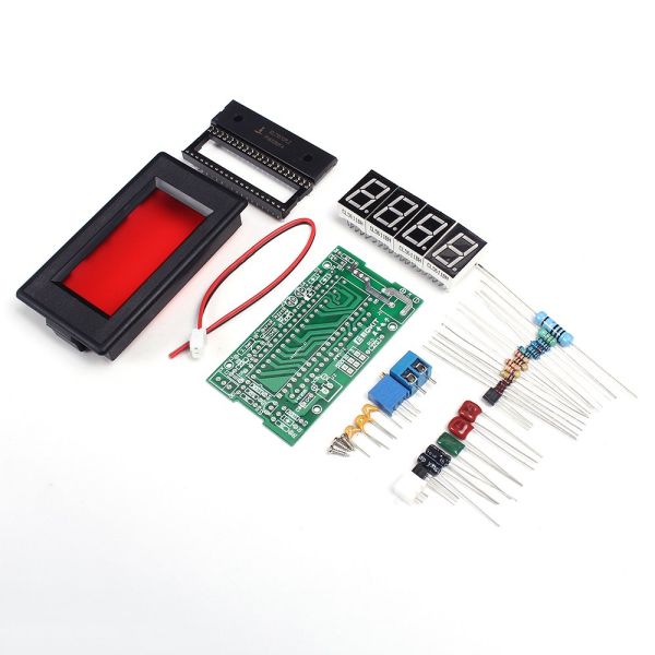
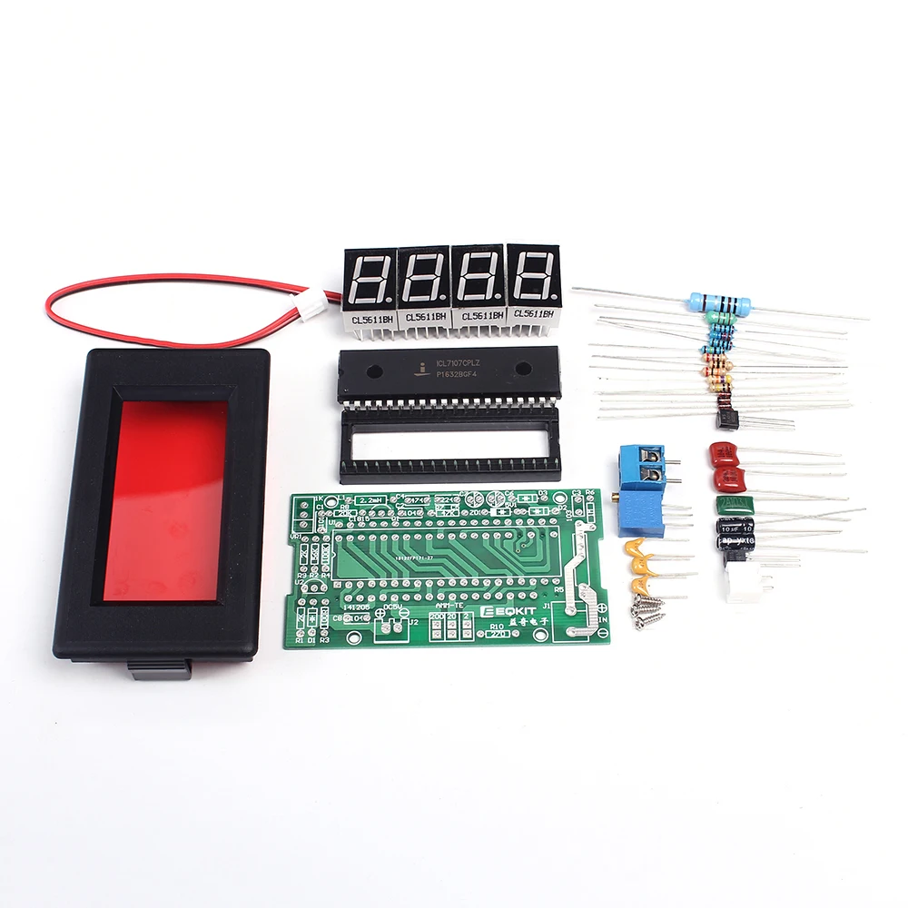
Product Introduction:
1.Model:AMM-TE
2.PCB Size:70.6*39mm
3.Display Window Size:51*24mm
4.Operating Voltage:DC 5V
5.Operating Current:35mA
6.Measurement Precision:+/-1mA
7.Measurement Range:0-2A
8.Overrange Display:the first bit displays 1 or -1
9.Display Color:red
10.Circuit Principle Picture:

Circuit Principle:
AMM-TE ammeter is mainly composed of ICL7107,power circuit,reference voltage source,input circuit and display circuit
1.ICL7107 is a BCD output integral type A/D conversion chip, its internal includes ;linear amplification,analog switch,oscillation,display driving etc.
2.Power circuit is divided into positive power and negative power;positive power is input by J2,C8 filtering;negative is composed of R8,Q1,L1,C6,C7,D2,D3 and ZD1,and generate -5V voltage is input by chip 26th pin
3.Reference voltage source is composed of R1,R2,VR1,R9 and U2;36-pin is reference voltage input pin;adjust VR1 potentiometer to let 36-pin voltage be 100mV
4.Input circuit is composed of J1,R5,R6 and C3.When the current of measured circuit passes through R5,it will generate a voltage on R5;this voltage will be input to chip 31-pin through R6 current limiting and be processed;C3 is input voltage filtering capacitor
5.Display circuit is composed of DS1-DS4,D1,D4;4 digital tubes can be drived directly by the chip,R10 is current limiting resistance of DS1-DS3 digital tubes decimal points
Finished Product Debugging:
1.After connecting with DC 5V (please notice the polarity),the digital tube will display -.000 or .000,this is normal
2.Use multimeter to measure the voltage between chip 36-pin and 35-pin,and adjust VR1 potentiometer let it be 100mV
Key Points Voltage Reference Value:
1.Chip 1-pin and 21-pin voltage 5V
2.Chip 36-pin and 21-pin voltage 100mV
3.Chip 26-pin and 21-pin voltage -5V
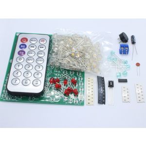
Packing List:


- Unit Type: piece
- Package Weight: 0.07kg (0.15lb.)
- Package Size: 1cm x 1cm x 1cm (0.39in x 0.39in x 0.39in)
Write Your Own Review
Discover More Products from Its Parent Categories: