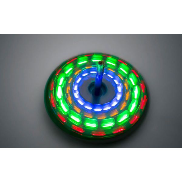

Fun DIY children’s gift desktop LED spinning top toy electronic learning kit flashing colorful light circuit board soldering practice kits
$3.00
Availability:
In stock
SKU
DIEK001
Payment Security

We are PayPal Verified
PayPal is a secure and trusted payment processing service that allows you to shop online. PayPal can be used at mondaykids.com to purchase items by Credit Card (Visa, MasterCard, Discover, and American Express), Debit Card , or E-check (i.e. using your regular Bank Account).
Product Model: MK-52-108
Power Supply Voltage: 6V (DC power supply, 2 x CR2032 battery)
Board Size: 52*52mm
Axis Length: 35mm
This fun DIY spinning top kit not only brings joy to children, but also allows them to learn about the working properties of capacitors and the working principles of transistors. In this application, the transistor plays the role of a switch, and the capacitor controls the base voltage of the transistor through its charging and discharging properties, thereby controlling the on and off states of the transistor.
The working process is as follows: when the battery is installed, the vibration switch S1 is in the open state, so the circuit does not work and all the LEDs are off. When the spinning top is spun, due to the centrifugal force, the vibration switch S1 is swung to the closed state, and the entire circuit begins to work. This is a astable multivibrator circuit. We can clearly find that the circuit is composed of two symmetrical sub-circuits. Resistors R1, R2, R3 are symmetrical to R6, R5, R4. Ceramic capacitors C1 and C2 are symmetrical, and transistors Q1 and Q2 are also symmetrical.
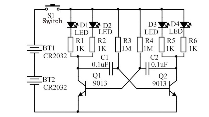
Theoretically, the operation result of this circuit should be that LED1, LED2, LED3, and LED4 are simultaneously lit and then simultaneously extinguished. This is because the charging and discharging time of the RC circuit composed of C1 and R3 is equal to that of the RC circuit composed of R4 and C2. If the base conduction voltage of the two NPN transistors Q1 and Q2 is 0.6V DC, the time required for C1 and C2 to charge to 0.6V is equal, which means that Q1 and Q2 will be turned on simultaneously, and LED1 to LED4 will be lit simultaneously. Because Q1 and Q2 are in the on state, the potential of one end of the collector of Q1 connected to C1 and the potential of one end of the collector of Q2 connected to C2 will become infinitely close to the potential of the GND terminal. Since one end of C1 is connected to the base of Q2 and one end of C2 is connected to the base of Q1, when the potential at both ends of C1 and C2 becomes infinitely close to the potential of the GND terminal, it will cause the base of Q1 and Q2 to be in the cut-off state. Because the base conduction voltage of Q1 and Q2 is 0.6V, and the potential drop of C1 and C2 causes Q1 and Q2 to not reach the on state, the entire circuit returns to the open state, and LED1 to LED4 are simultaneously extinguished. When Q1 and Q2 are in the cut-off state, the current charges C1 through R3 and charges C2 through R4. When the charging voltage reaches the threshold of transistor conduction, the transistor is turned on again, all LED lights are lit simultaneously, and then extinguished immediately, and this cycle repeats.
In reality, every electronic component has intrinsic tolerances. There are no two capacitors or resistors in the real world with exactly the same values. In this circuit, even though capacitors C1 and C2 are both labeled as 0.1μF, and resistors R3 and R4 are both labeled as 1MΩ, there are still differences between C1 and C2, and between R3 and R4. These differences result in the actual charging and discharging time constants not being the same. This leads to a situation where one of the capacitors, say C1, reaches the transistor base conduction threshold before the other. If C1 charges to 0.6V before C2, then transistor Q2 will conduct first, lighting up LEDs 3 and 4, while LEDs 1 and 2 remain off. As Q2 conducts, its collector potential approaches the GND potential, causing C2 to discharge. This current change makes C2 act as a short circuit, pulling down the base voltage of Q1, keeping Q1 open, and LEDs 1 and 2 remain off. As this is a DC circuit, once Q2 conducts, the circuit current will gradually stabilize. In a stable DC circuit, C2 acts as an open circuit and begins to charge. When the voltage accumulated by C2 reaches 0.6V, Q1 conducts, lighting up LEDs 1 and 2. As Q1 conducts, its collector potential approaches the GND potential, causing C1 to discharge. This pulls down the potential across C1 to near GND, and since one end of C1 is connected to the collector of Q2, this pulls down the base voltage of Q2 below the threshold, cutting off Q2, and LEDs 3 and 4 go from on to off. Once the current through Q1 stabilizes, C1 acts as an open circuit and begins to charge. When C1 charges to 0.6V, Q2 conducts, Q1 cuts off, LEDs 1 and 2 go off, and LEDs 3 and 4 light up. This process repeats in a cycle.
Through the above analysis, we can learn how to utilize the charging and discharging properties of capacitors and the switching properties of transistors to create a astable multivibrator circuit. This allows us to gain a deeper understanding of the role of capacitors.
Write Your Own Review
Discover More Products from Its Parent Categories: