Complete Introduction to Resistors
November 13, 2023
Complete Introduction to Resistors
What is resistor?
Resistor is a substance which has ability to oppose the electric current to flow through. In other words, resistor is used to limit current and divide voltage in a practical circuit. There are two types of resistors we commonly see around us, one is Linear Resistors another one is Non-linear Resistors. The difference between linear resistors and non-linear resistors is that linear resistor is with a constant resistance while non-linear resistor is with non-constant resistance.
What is resistance?
Resistance is used to represent the value of resistors mentioned above. People named the unit of resistance after ohm that in order to in honr of the German physicist Georg Simon Ohm for the contribution to the discovery of Ohm’s Law. It is often denoted by the Greek symbol Ω
In this content we only discuss about Linear Resistors.
What’s linear resistors?
For linear resistors, they remain constant resistance (constant ratio of voltage to current) no matter how much the voltage and current are changed applied to them. For example, a resistor was given with unknown resistance, let us apply a 10V voltage to it, and use an ammeter to measure out that the current flow through it is 0.001A, i.e. 1mA. According to Ohm’s Law,
at that moment the resistance is 10V÷0.001A = 10000Ω ≈ 10kΩ (We use approximately equal to symbol here because in fact all the resistors have tolerance value).
Once we increase the voltage to 20V, and use an ammeter to measure out the current is 0.002A, i.e.2mA.
According to Ohm’s Law, the resistance is 20V÷0.002A = 10000Ω ≈ 10kΩ.
As this resistor has a constant resistance value of 10kΩ however the voltage and current vary. We call this resistor linear resistor.
Linear resistors are composed of fixed value resistors and variable resistors.
Fixed Resistors
Fixed value resistors are the types of resistors that their values are fixed and unable to change manually. We mainly introduce the fixed value resistors which commonly see around us in this article.
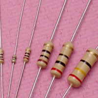
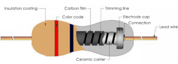
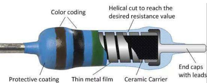
Carbon Film Resistors
Carbon film resistors contains an insulating ceramic carrier rod. A thin pure carbon layer which plays a role in resistive function is deposited on this rod. There is a helical cut in carbon film layer to determine the value of resistance. We will explain why minutes later. Typical tolerance are among ±2%, ±5%, ±10%, ±20%. What is tolerance of a resistor? For example, a linear resistor is marked a 100Ω and its tolerance is ±5%, then its real resistance should be from 100*(1-5%) to 100*(1+5%), i.e. 95Ω to 105Ω.
Advantages of Carbon Film Resistors
- Low tolerance
- Low price
- Wide operating range (from 1Ω to 10MΩ)
Disadvantages
- High negative temperature co-efficient of resistance(±200 - >±1500ppm/°C)
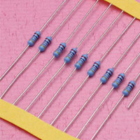
Metal Film Resistors
The structure of metal film resistors is similar to carbon film resistors. The main difference is that there is metal layer deposited on the ceramic carrier rod instead of carbon. Metal film resistors have lower tolerance value compared to carbon film resistors. Typical tolerance are among ±0.1%, ±0.25%, ±0.5%, ±1% and ±2%. Metal film resistors are with very low temperature coefficient (±2 ppm/°C). As they are reliable in operation and with very low noise level, they mainly be used in high frequency applications.

Advantages of Metal Film Resistors
- Low cost
- Less noise than carbon film resistor
- Wide operating range
- Good stability
- Low tolerance
- Low temperature co-efficient of resistance
Applications of metal film resistor
- Premium Speaker
- Computer
- Laboratory Apparatus
- Aerospace Field
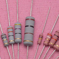
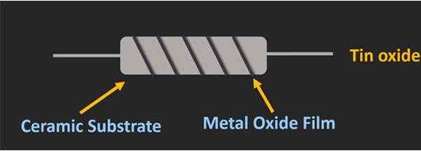
Metal Oxide Resistors
Metal oxide resistors is quite different from carbon film resistors and metal film resistors in manufacturing process. Metal oxide resistors are made by coating the ceramic rod(substrate) with Tin Chloride (Tin Oxide) on the metal film. From a chemical point of view, this is an oxidation process. Metal oxide resistors have a wide range of resistance with high temperature stability. Besides, they have low noise level and could be used at high voltage. Typical tolerance are among ±1%, ±2%, ±5%, ±10%, the tolerance and noise level and temperature co-efficient (±50 - >±100 ppm/°C) are poor than metal film resistors, but the working temperature is much higher than metal film resistors.
Advantages of Metal Oxide Film Resistors
- Operate at higher temperatures
- Generate very low noise
- High stability and reliability
- Maximum power and voltage are greater than other film resistors
Applications of metal oxide film resistor
- Used in high temperature and high surge applications
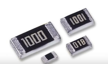
Surface-mount Resistors (SMT Resistor)
SMT resistors are rectangular in shape and have a small size compared to through-hole resistors (resistors come with long, pliable leads). SMT resistors are consist of two metalized contacts at either end of the main ceramic body. The SMT resistors are made by overlaying the surface of ceramic body with resistive material – generally metal oxide film or metal film. In SMT resistors, the resistance value is determined by the length, thickness, and material of the thin resistive film. The temperature co-efficient and tolerance of SMT are dependent on what material is adopted to form the thin resistive film (please refer to metal film part and metal oxide film part).

Variable Resistors
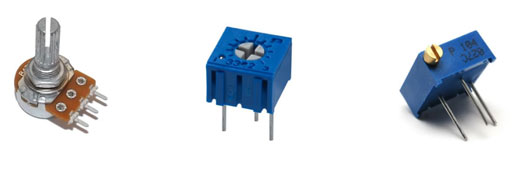
Variable resistors are also known as Potentiometer or rheostats that they have a range of resistance allowed to be adjusted during the process of usage. Typically, they have 3 terminals, two terminals are connected to both ends of the resistive part, the third is connected to the wiper (sliding contact). The output voltage is determined by the position of the wiper. Single turn rotary can be commonly seen in our daily life, it is often used in audio volume control, car air conditioner control as well as many other applications. Several kinds of material can be used to manufacture Potentiometer, including cermet, conductive plastic and metal film etc.
How to achieve the desired resistance value while manufacturing process?
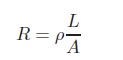
As we’ve mentioned above, that both of metal film and carbon film resistor have a helical cut on film layer that is used to determine the resistance value, i.e. the thickness of film layer and width of helical film cut determine the resistance value. For a conductor, the resistance is proportional to its length and inversely proportional to its cross-sectional area. Making a conductor longer increases its resistance. Making it thicker decreases the resistance. The constant of proportionality is a property of the material, known as resistivity.
In formula form, it is:
 (1.0.0)
- R- Resistance in ohms(Ω)
- ρ- The resistivity of the material, measured in ohm-metres
- L- Length of the sample, in metres.
- A- Area of the sample (such as the cross-sectional area of a wire), in square metres.
Let us analyze the Resistance of film resistors with the formula above.
As we can see that the helical film cut with more width provide less total length of the resistive element. Please note that width of helical cut is not about the groove part. The letter L represents the total length of resistive element, A represent the thickness of film layer. According to the formula we can learn that the desired resistance value can be achieved by adjusting the width of helical film cut and thickness the film layer, i.e. the resistance of film resistor is inversely proportional to the width of helical film cut, the resistance of film resistor is inversely proportional to the thickness of the resistive film layer. That is, as thickness increases, resistance decreases, as width of helical film cut increases, resistance decreases.
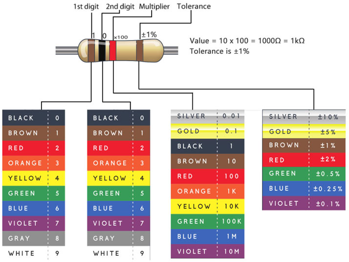
How to Read Color Codes from Resistors?
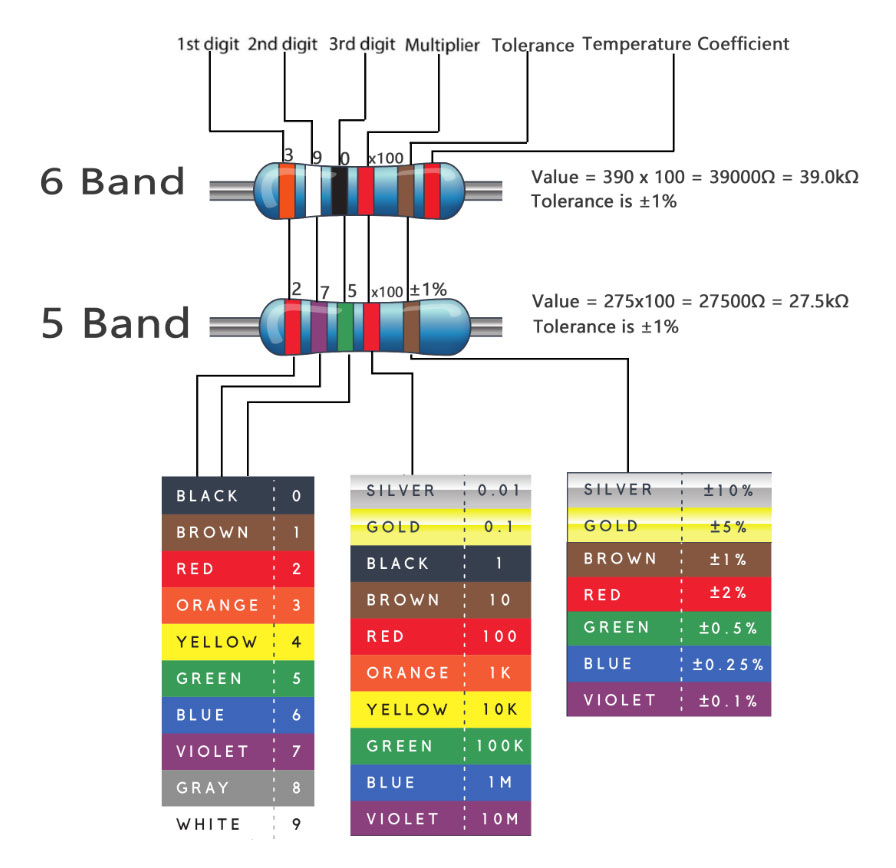
Practically all resistors with wire lead for through-hole mounting use color-band pattern that used to indicate resistance value, tolerance, and sometimes even the temperature coefficient. There can be anywhere from three to six colored bands on the body of a resistor, with four bands being the most common variation, though you will also find five band and six band resistors sometimes. It is quite easy to read the resistance of resistor from colored bands chart. To read the bands from left to right sequentially to get the resistance value, tolerance, and even temperature coefficient. Many people may be confused in a practical scenario that which side of resistor is left. In general, the tolerance band is separated from the rest of the bands by a very slightly larger gap. Sometimes there is often a subtle difference in (location of) the tolerance ring, but not always too clear, you may want to verify the found value with your multimeter.
For SMT resistors, there are three to four characters, numbers or letters, printed on the top surface of it. If the three characters you're seeing are all numbers, you're probably looking at a resistor marked with E24 Standard.
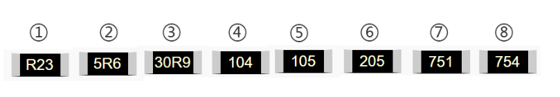
In the above pictures, the resistors should be as showing below:
①0.23Ω ②5.6Ω ③30.9Ω ④100kΩ (10x104) ⑤1MΩ (10x105) ⑥2MΩ (20x105) ⑦750Ω (75x101) ⑧750kΩ (75x104)
Another resistor can be commonly seen around us is marked with E96 Standard. E96 resistors is marked with 3 characters, 2 numbers at the beginning and a letter at the end.
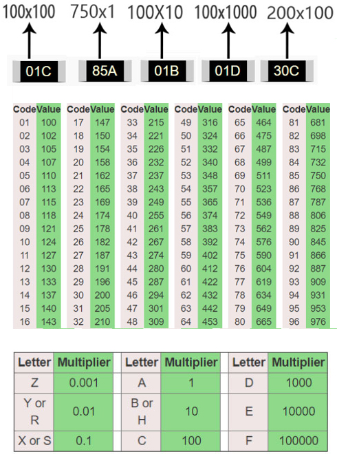
As the above pictures shows, let’s split 01C into 01 and C. We can learn from the chart that 01 represents 100, and C represents 100, so 01C means 100x100, is equal to 10kΩ.
Effect of temperature on resistance
From Equation(1.0.0), resistance of a conductor changes with the size of the conductor (e.g. thicker wires have less resistance to current flow than thinner wires). However, the resistance is actually given at a particular ambient temperature. This is because the temperature of the resistor also affects its value. While a resistor working within the maximum temperature, small change in temperature will cause change in resistance, this is because the manufacturer has chosen a material having a resistivity not greatly influenced by temperature. That is, the material (and so the resistor) has a low TEMPERATURE COEFFICIENT. In other words, there is only a small change in value per °C. This change in value is normally defined in Parts Per Million per degree Centigrade (ppm/°C,). For example, a 1kΩ resistor with temperature coefficient 50ppm/°C (50Ω for every 1MΩ) that the change in temperature of every 1°C will cause less than 0.05Ω of change for every 1KΩ of its value.
How Temperature affect resistance
The flow of current is actually the movement of electrons from one atom to another under the influence of an electric field. Electrons are very small negatively charged particles and will be repelled by a negative electric charge and attracted by a positive electric charge. Therefore, if an electric potential is applied across a conductor (positive at one end, negative at the other) electrons will "migrate" from atom to atom towards the positive terminal. Only some electrons are free to migrate however. Others within each atom are held so tightly to their particular atom that even an electric field will not dislodge them. The current flowing in the material is therefore due to the movement of "free electrons" and the number of free electrons within any material compared with those tightly bound to their atoms is what governs whether a material is a good conductor (many free electrons) or a good insulator (hardly any free electrons). The effect of heat on the atomic structure of a material is to make the atoms vibrate, and the higher the temperature the more violently the atoms vibrate. In a conductor, which already has a large number of free electrons flowing through it, the vibration of the atoms causes many collisions between the free electrons and the captive electrons. Each collision uses up some energy from the free electron and is the basic cause of resistance. The more the atoms jostle around in the material, the more collisions are caused and hence the greater the resistance to current flow.In a material where the resistance INCREASES with an increase in temperature, the material is said to have a POSITIVE TEMPERATURE COEFFICIENT.When resistance FALLS with an increase in temperature, the material is said to have a NEGATIVE TEMPERATURE COEFFICIENT.
Maximum Voltage and Rated Power Can be Applied to a Resistor
Rated Voltage is the maximum value of direct-current(DC) continuous working voltage or an approximately sine-wave root-mean-square(RMS) alternating-current(AC) continuous working voltage capable of being applied to resistors at the rated ambient temperature, as determined from the following formula:
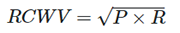 (1.0.1)
Where: RCWV = Rated DC or RMS AC continuous working voltage at commercial-line frequency and waveform (unit is volt)
- P = Power rating (watt)
- R = Nominal Resistance (ohm Ω)
- In no case shall the rated DC or RMS AC continuous working voltage be greater than the applicable maximum value.
Rated power is the maximum amount of power that can be continuously loaded to a resistor at a rated ambient temperature. Network and array products have both rated power per package as well as per element.
In some cases, beginners will see that the instance that Rated Voltage is contradictory from Rated Power according to the formula (1.0.1).For example, a 27Ω resistor has 50V voltage rating and 0.2W power rating listed in datasheet, place the values into the formula 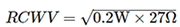 ,RCWV = 2.32V. Obviously, 50V ≠ 2.32V
They may ask that why would the voltage rating list as 50V, not 2.32V?
However, Rated Power is completely independent of of Rated Voltage. You have to conform to both specs. If placing the maximum voltage across the resistor results in more power than the spec allows you have to reduce the voltage until you meet the spec. Likewise you can't increase the voltage above the rating just because you're not hitting the maximum power limit.It comes to a conclusion that low resistance value resistors are limited by their rated power(you can not reach their rated voltage), while high resistance value resistors are limited by their rated voltage. It is not difficult to understand this conclusion,when in case of with a low resistance value resistor the is less than the rated voltage in datasheet, so this resistor is limited by rated power. Likewise, with a high resistance value resistor, the root-mean-square of P x R is greater than the rated voltage in datasheet, this resistor is limited by rated voltage.
Maximum Overload Voltage
Maximum overload voltage is the maximum value of voltage capable of being applied to resistors for a short period of time in the overload test. If you do not apply the voltage continuously, you can put a higher voltage on a resistor for a short duration. Resistor manufacturers define an STOL (short-time-overload) condition, the degree of which varies depending on the type of resistor. For most film resistors, STOL is 2.5 times the rated voltage, or 6.25 times the rated power, for 5 sec. For high-voltage resistors, STOL is commonly 1.5 times the rated voltage, or 2.25 times the rated power, for 10 sec. Refer to your resistor's product sheet to see how the manufacturer defines STOL and to find the maximum percentage of change in resistance that can occur when you apply the STOL voltage. However, it should not exceed the maximum overload voltage. Keep the resistors working on overload voltage can cause permanent damage and can melt the solder joints that hold the part in place, and even cause fire disaster.
Basic Circuit Units of Resistors
Resistors can be paired together in either a series connection, a parallel connection or combinations of both series and parallel, to form more complex resistor networks that they create a total resistance which can be calculated using the corresponding mathematical equations which will be mentioned in the following.
Resistor in Series and Voltage Division
As we can see in Fig.0.0.1, the three resistors are in series, they have the Same Current i flowing through them. That means,IR1=IR2=IR3.
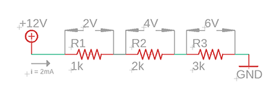 (Figure 0.0.1)
According to Ohm’s Law,we get
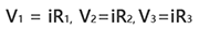 (2.0.0)
The voltage across each resistor connected in series conforms to different rules to that of the series current. We can learn from the above circuit that the total supply voltage across the resistors is equal to the sum of the potential differences across R1 , R2 and R3
V = V1 + V2 + V3 =12V (2.0.1)
Combining Equation(2.00) and (2.0.1), we get,
V = iR1 + iR2 +iR3 (2.0.2)
Or
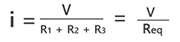 (2.0.3)
We can see that the equivalent resistor Req = R1 + R2 +R3 = 1kΩ + 2kΩ + 3kΩ = 6kΩ
The three individual resistors above can be replaced by just one single equivalent resistor which will has a value of 6kΩ.
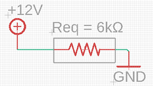 Figure (0.0.1.1)
The three individual resistors above can be replaced by just one single equivalent resistor which will has a value of 6kΩ (just like Fig. (0.0.1.1) shows). Where four, five or even more resistors connected in series, the equivalent resistance is the sum of the individual resistors. The more resistors added to the series, the greater the equivalent resistance.
Equivalent Resistance can be defined as a single value of resistance that can replace any number of resistors in series without altering the values of the current or the voltage in the circuit and has the same effect on the circuit as the original combination of resistors.
For N resistors in series then the equation is,
Rtotal = R1 + R2 + R3 + ... + Rn (2.0.4)
We can learn from the equation(2.0.4) that the total resistance (Rtotal) of resistors connected in series will always be GREATER than the resistance value of the largest resistor. In our example above Rtotal = 6kΩ whereas the largest value resistor is only 3kΩ.
For N resistors in series, the total voltage in a series circuit which is the sum of all the individual voltages added together is given as:
Vtotal = iR1 + iR2 + iR3 + ...+ iRn = V1 + V2 + V3 +...+ Vn (2.0.5)
Voltage Divider
Series resistor networks can also be considered as Voltage Dividers.
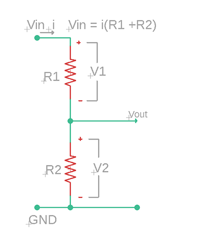 (Figure 0.0.2)
Figure 0.0.2 is a typical voltage divider circuit. To determine the voltage across each resistor in Fig. 0.0.2,we substitute Eq. (2.0.4) and Eq. (2.0.5) and obtain
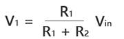 (2.0.6)
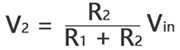 (2.0.7)
From the Eq. (2.0.6) and Eq. (2.0.7) we can know that the source power Vin is divided among the resistors in direct proportion to their resistances; larger resistance will have a larger voltage drop across it, while a smaller resistance will have a smaller voltage drop across it. This is called the principle of voltage division, and this circuit is called a voltage divider. Voltage Divider Circuit is the simplest way of producing a lower voltage from a higher voltage, and is the basic operating mechanism of the potentiometer.
Voltage dividers have many applications, they are among the most common of circuits electrical engineers use. The most commonly seen applications are Potentiometers, measuring the values of sensors such as Thermistor, Photocell, Flex Sensors, Force-Sensitive Resistors. Just by adding another resistor to the sensor to create a voltage divider like Fig. 0.0.2 and then you can calculate the sensor resistance by reading Vout using analog-to-digital converters circuit module to obtain the change of environment variable (temperature, pressure, intensity of light etc.) that, the sensor is measuring.
Resistors in Parallel and Current Division
Resistors connected in parallel is NOT working as the same as resistors connected in series. Series resistors have the same current flowing through each resistor while resistors connected in parallel have the same voltage applied to each resistor. N resistors connected in series create N times of attenuation on voltage but N resistors connected in parallel just only have one time of attenuation on voltage. It is not difficult to understand this point of view. As in series of N resistors, when currents flowing through R1, the Electric Potential reduces V1, then the current via R2, electric potential reduces V2; when the current via Rn, electric potential reduce Vn, so V-V1-V2-V3-...-Vn = 0.
For resistors connected in parallel, the terminals on the same side of each resistor have the same electric potential. Voltage across each resistor can be calculated using high electric potential minus low electric potential, in Fig. (0.0.2), high electric potential is 12 V, low electric potential is 0V (Ground or GND). So the voltage across each resistor is 12V – 0V = 12V. Where we add N resistors to be connected in parallel the voltage across each resistor will also be the same.
You may ask why would the electric potential on the same side of each resistor be the same
As the wire resistance is approximately equal to zero, there is no voltage drop across the wire, that means the electric potential on each point of the wire is the same. In Fig. (0.0.2), each left side of the resistor are connected with a wire, each right side of the resistor are connected with another wire. So in the case of resistors connected in parallel the electric potential on the same side of each resistor be the same.
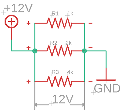 Figure (0.0.3)
Let us look at Fig. (0.0.2), from Ohm’s Law,
V = i1R1 = i2R2=i3R3
or,
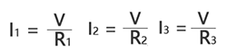 (2.0.8)
In parallel circuits, total current I is the sum of currents through each path,
I = i1 + i2 + i3 (2.0.9)
Substituting Eq. (2.0.8) into Eq. (2.0.9), we get
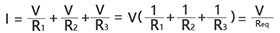 (2.1.0)
Where Req is the equivalent resistance of the resistors in parallel,
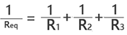 (2.1.1)
For N resistors connected in parallel, the equivalent resistance is,
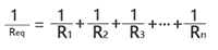 (2.1.2)
Note that Req is always smaller than the resistance of the smallest resistor in the parallel combination. In the case of R1 = R2 = R3 = …Rn=R, the equivalent resistors Req = R/N. To prove Req is always smaller than the resistance of the smallest resistor in the parallel combination is quite easy. Consider just only one resistor R1 in the circuit,
The total current Itotal1 =  (2.1.3)
From Eq. (2.1.3) and Eq. (2.1.2),
Itotal2 – Itotal1 = (V/R1 + V/R2) - V/R1 = V/R2, as V/R2 > 0, so Itotal2 – Itotal1 > 0;
or
Itotal2 > Itotal1 (2.1.4)
From Ohm’s Law,
Itotal2 = V/Req, Itotal1 = V/R1 (2.1.5)
From Eq. (2.1.4) and Eq. (2.1.5),
V/Req > V/R1, 1/Req > 1/R1
or
Req < R1, likewise, Req < R2 (2.1.6)
As we know, If the resistors are connected in parallel then there will be the same voltage across each resistor. That implies when we add a new parallel resistor Radd the circuit that a current Iadd will be generated and make an increment to the total current Itotal. As voltage V is a constant in this context, current Itotal in increases, the equivalent resistance Req decreases. The more parallel resistors you add to the circuit, to more equivalent resistance decreases. We can extent the result in Eq. (2.1.6) to the general case of a circuit with N resistors in parallel. The relationships between Req and R1,R2,R3…Rn is,
Req < R1, Req < R2, Req < R3,…, Req < Rn
Current Divider
Some beginners may ask why parallel circuit is known as current divider. Well, this part will give you an explanation using mathematical equations in the following.
In a circuit has N parallel resistors, Itotal is,
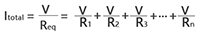 (2.1.7)
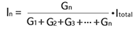
from Ohm’s Law, the current In through Rn is,
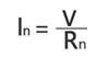 (2.1.8)
we derive the following equation from Eq. (2.1.8),
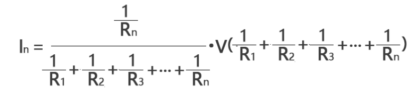 (2.1.9)
It is often more convenient to use conductance rather than resistance when dealing with parallel resistors circuits. Conductance is the degree to which an object conducts electricity, calculated as the ratio of the current that flows to the potential difference present. This is the reciprocal of the resistance, and is measured in siemens or mhos, denoted by G.
G1=1/R1, G2=1/R2, G3=1/R3,…, Gn=1/Rn.
We can express Eq. (2.1.8) as
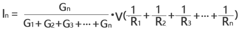 (2.2.0)
Combining Eq. (2.1.1) and Eq. (2.2.0), we get
 (2.2.1)
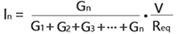
Combining Eq. (2.1.0) and Eq. (2.2.1), we get
 (2.2.2)
Eq. (2.2.2) shows that the total current Itotal is shared by the resistors is inversely proportional to their resistances. This is known as the principle of current division, this parallel circuit is known as current divider. From Eq. (2.2.2) we learn that larger current flows through the smaller resistance.
Resistor Networks
Resistor networks is the combinations of series and parallel resistors. In general, you may need to combine resistors in series and parallel and reduce a resistive network to a single equivalent resistance for analysis of the resistance between the designated terminals.
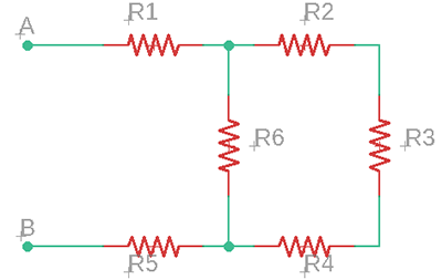 Figure (0.0.4)
To get equivalent resistance Req between the designated terminals A and B in Fig. (0.0.4), we need to combine resistors in series and in parallel. In this case, R2,R3,R4 are all in series and can be added together, they can be turned into one with a resistance of (R1+R2+R3). Make the circuit like Fig. (0.0.5)
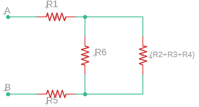 Figure (0.0.5)
From Fig. (0.0.5), we can see that (R2+R3+R4) are in parallel with R6, they can be turned into one with a resistance of R6∥(R2+R3+R4), just like Fig. (0.0.6) shows. The symbol ∥ is used to indicate a parallel combination, if R1 is in parallel with R2 then it can be written as R1∥R2.
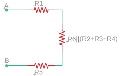 Figure (0.0.6)
The remaining resistors in Fig. (0.0.6) are all in series that can be added together, they can be turned into one with a resistance of “R1+(R6∥(R2+R3+R4))+R5”, as Fig. (0.0.6) shows.
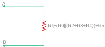 Figure (0.0.7)
we can see that resistor networks can be simplified by identifying series and parallel resistors. The equivalent resistance between the terminal A and B is, R1 +(R6∥(R2+R3+R4)) +R5. When dealing with other resistor networks you just need to do the similar thing to simplify the circuits step by step that combine resistors in series and parallel and reduce the resistive network to a single equivalent resistance.
Creative Commons tutorials are CC BY-SA 4.0 License