Complete Introduction to Inductors
December 19, 2023
Complete Introduction to Inductors
In the realm of passive components, inductors are considered relatively complex components compared to passive elements like resistors and capacitors. There are four main reasons why inductors are often regarded as more intricate:
- 1. Complex structure: Inductors have a more intricate structure than resistors and capacitors. They consist of a coil, magnetic core, and casing. The coil is made of wire, while the magnetic core is composed of materials such as iron or nickel. The casing is typically made of plastic or metal. The inductance of an inductor depends on factors such as the number of coil turns and the material and shape of the magnetic core.
- 2. Multiple parameters: Inductors have more parameters than resistors and capacitors. These parameters include inductance, inductance coefficient, quality factor, and distributed capacitance. All these parameters affect the performance of an inductor.
- 3. Complex characteristics: Inductors exhibit more complex characteristics than resistors and capacitors. They possess nonlinearity and energy storage properties. Nonlinearity refers to the fact that the inductance of an inductor varies with changes in current. Energy storage capability refers to the ability of an inductor's magnetic field to store energy.
- 4. Diverse applications: Inductors find more diverse applications compared to resistors and capacitors. They are widely used in electronic circuits such as filtering circuits, resonant circuits, and coupling circuits. There are also various types of inductors available, including air core inductors, iron core inductors, and ferrite beads.
Some novice electronics enthusiasts often struggle to understand how to use inductors when they encounter this component in the study of analog circuits. They find it difficult to determine the appropriate situations to introduce an inductor to meet their design requirements. Additionally, they are unsure how to calculate and select the right specifications and parameters for an inductor. This article aims to provide a comprehensive explanation of inductors, helping you gain a better understanding of their usage and how to effectively utilize them.
Before discussing inductors, let's talk about two phenomena:
- Phenomenon One - Magnetic Effect of Electric Current: When an electric current flows through a conductor, it generates a magnetic field around the conductor. This is because the flowing current involves the movement of electric charges, which in turn creates a magnetic field. This phenomenon, where a magnetic field is produced around any conductor carrying an electric current, is known as the magnetic effect of current.
- Phenomenon Two - Magnetic Induction: When a changing magnetic field passes through a conductor, an induced electromotive force (emf) is generated at the ends of the conductor. If the conductor is formed into a closed loop, this emf drives the flow of electrons, resulting in an induced current. By using the right-hand rule, we can determine that the direction of the induced current in Figure 2 is from A to B. An interesting situation arises here. From Figure 1 of phenomenon one, we can observe that the magnetic field generated by the induced current in Figure 2 has magnetic field lines that are opposite to the magnetic field lines of the magnet. In other words, the magnetic field generated by the induced current opposes the original magnetic field, which can mitigate the motion of the conductor, leading to a slower change in the current of the conducting wire. This effect ensures that the induced current does not change too rapidly, but also doesn't decay too slowly, resulting in a smooth curve.
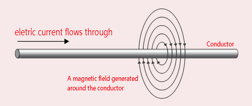 Fig. 1
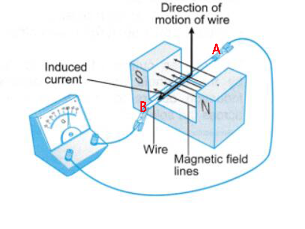 Fig. 2
It is said that electricity and magnetism can induce each other, which means that when current passes through the coil, an induced voltage will be induced on the same coil. The induced voltage will react on the current passing through it, this back Electric and magnetic fields(EMF) acts like a counterforce, slowing down the rate of change of current, so that the current flowing through it gradually reaches its final value, that is to say, inductors oppose changes of non-steady state DC current but let the steady state DC current easily goes through, i.e. for the steady state DC current, the inductor acts like a straight conductor wire. It is precisely because of this nonlinear characteristic of the coil that when we use the coil in circuit design, we often need to go through complex formula calculations and repeated experimental adjustments to select the appropriate coil.
An inductor, also called a coil, choke, or reactor, is a passive two-terminal electrical component that stores energy in a magnetic field by inducing a magnetic field within its core when electric current flows through it. An inductor typically consists of an insulated wire wound into a coil.
 Fig. 3
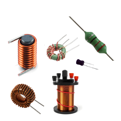
In Fig.1 of Phenomenon one, we observe that when the wire is straight, the magnetic field generated by the current passing through it is circular, with the magnetic field lines being perpendicular to the wire. This raises a question: What happens to the magnetic field when the wire is bent?
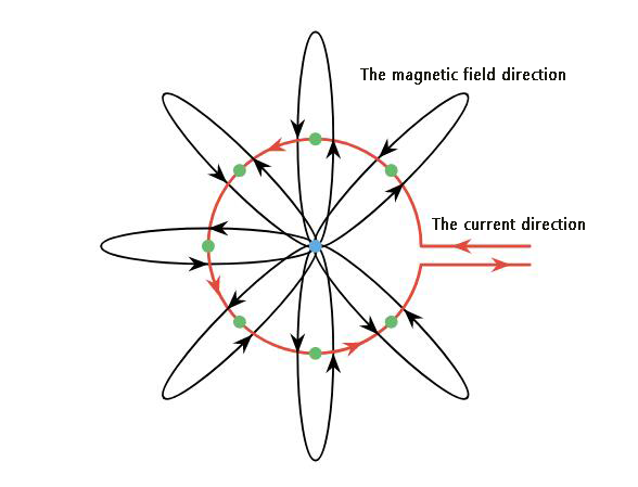 Fig.4
Fig.4
From Fig. 4, it can be seen that when the wire forms a circle, the magnetic field lines generated converge at the center of the circle, reaching their maximum intensity. We can observe that the area surrounding the conductor is filled with magnetic flux linkage, denoted by the symbol Φ. At this point, the coil in Fig. 3 exhibits inductance, denoted by the symbol L, which represents its ability to resist changes in current. The equation for inductance is as follows:
-
(eq. 1.0)
- L: The self-inductance of the coil with units of Henry, (H)
- N: The number of turns in a coil
- Φ: The magnetic flux linkage through the coil in Webers
- i: the instantaneous current flowing through the coil at a specific moment
However, the inductance of an inductor also depends on its physical dimension and construction and the permeability of its core. Formulas for calculating the inductances of inductors of different shapes are derived from electromagnetic theory and can be found in standard electrical engineering handbooks. Below it is the formula of the inductance of the long and straight solenoids, where the length (ℓ) is much greater than the diameter of the coil:
-
(eq. 1.1)
- N: The number of turns in a coil
- ℓ: The length of the coil in meters
- A: The cross-sectional area of the coil in m²
- μ: Permeability of the core material in meters
In electromagnetic induction, electromotive force (emf) is generated by a changing magnetic field over time. When the magnetic field changes, it induces an emf in a conductor. The magnitude of the induced emf is directly proportional to the rate of magnetic field change. The positive or negative sign of the induced emf indicates the direction of the magnetic field change. When the magnetic field strengthens, the induced emf is positive, indicating an increase in emf. Conversely, when the magnetic field weakens, the induced emf is negative, indicating a decrease in emf.
The relationship between self-induction voltage (V), the number of turns in a coil (N), the magnetic flux (Φ), and the rate of change of the magnetic flux () is governed by Faraday's Law of Electromagnetic Induction:
(eq. 1.2)
By combining equations 1.0, 1.1, and 1.2, we can derive the formula for self-induction voltage as follows:
-
(eq. 1.3)
- N: The number of turns in a coil
- ℓ: The length of the coil in meters
- A: The cross-sectional area of the coil in m2
- μ: Permeability of the core material in meters
- L: The self-inductance of the coil with units of Henry, (H)
- Φ: The magnetic flux linkage through the coil in Webers
- di/dt: the Currents rate of change in amps/second
In real-life applications, one Henry is a large value. The inductors we commonly use are usually in the milli-Henry, micro-Henry, and nano-Henry ranges.
1mH = 1 milli Henry = 1/1000 henry.
1μH = 1 micro-Henries = 1/1,000,000 henry.
1nH = 1 nano-Henries = 1/1,000,000,000 henry.
The relationship between sub-units of the Henry and Henry is in below chart:
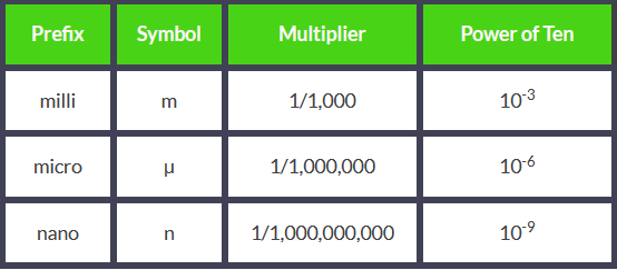 (Fig.5)
The eq.1.3 is not elegant and simple enough, according to eq1.0 and eq.1.2 it can be simplified as below:
as it is the back emf voltage, so:
(eq.1.4)
From eq1.4, we can learn that if current is allowed to pass through the inductor, it is found that the emf voltage across the inductor is directly proportional to the time rate of the change of the current, if the current is a steady state DC current, the time rate of the change of the current is 0, therefore, for the steady state DC current, the emf voltage is 0, i.e. for the steady state DC current, an inductor can be regarded as a straight conductor wire. An inductor does not oppose the steady state DC current to pass through. If a circuit has an inductance of one Henry will have an emf of one volt induced in the circuit when the current flowing through the circuit changes at a rate of one ampere per second.
About the Time Constant of the Inductor
In the previous article introducing capacitors, we mentioned the concept of Time Constant, which is also present in inductors that possess energy storage characteristics. The time constant of an inductor, represented by the symbol τ(tau), measures the time required for the current to rise or decay in an inductive circuit. It is determined using the following formula:
-
(eq.1.5)
- τ(tau) is the time constant in seconds
- L is the inductance in Henries
- R is the resistance of the coil in ohms
The time constant (τ) of an inductor plays a crucial role in various circuits and systems, influencing their behavior and performance. We will explain why later.
In order to help you better understand the time constant of inductors, let's consider the following circuit as an example:
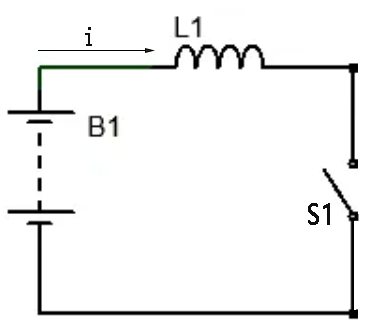 (Fig.6)
When the switch S1 is open, there is no current flow through the inductor L1, the rate of change of current (di/dt) in the coil is zero, therefore, the self-induced back-emf voltage VL=0.
Now, we close the switch S1, (stage 1)at the time t=t0, the current begins to flow through the inductor coil。(stage 2)at the time t = t1, as we know, it will be a self-induced voltage across the coil to fight against the applied voltage, according to Faraday’s equation, the self-induced voltage V = -L(di/dt). (stage 3)at the time t=t2, When the current reaches its maximum value to become the steady DC current state, rate of change of current (di/dt) is zero, the self-induced voltage is zero, there is no self-induced back emf voltage to oppose the current flow through but the coils DC resistance still exists to oppose it.
Correspondingly, when the switch S1 open, the current flow the inductor coil starts to decay, as we know, the inductor has the feature to fight against the changing of the current, therefore, to oppose this collapse, the inductor induces an emf that drives a current in the opposite direction of the original current according to Faraday's law of induction. The understand the above processes better, you can refer to the below graph:
 (Fig.7)
Now we go back to the time constant τ, in the waveform timing diagram above, the period from t0 to t1 represents the time constant of the inductor.it tells you how quickly the current in an inductor changed when the applied voltage changes, influencing their behavior and performance. The term 'time constant' is generally used in the following circuits:
- Charging and Discharging Circuits:RL (resistor-inductor) charging circuits, the time constant determines how quickly the inductor's current reaches its steady-state value. A higher time constant indicates slower charging/discharging, while a lower time constant signifies faster changes
- Filters and Signal Processing Circuit: Inductors with specific time constants can be used to design filters that block or pass specific frequencies in a signal. For example, audio crossovers utilize inductors with different time constants to separate bass, midrange, and treble frequencies
- Timing Circuits and Oscillators Circuit: The time constant can be used to create timing circuits that delay signals for a predetermined period. Additionally, circuits with specific inductor-resistor combinations can oscillate at specific frequencies, forming the basis of oscillators used in various applications
- Energy Storage and Release Circuit: With large time constants it can store and release energy over a longer duration. This principle is utilized in power converters and switching circuits to regulate and control energy flow
- Motor Control and Power Electronics: it plays a vital role in controlling the current and speed of electric motors. Their time constants influence the torque and response characteristics of the motor. Additionally, power electronic circuits rely on inductors' time constants for various switching and protection functions
As we can see, the formula for the time constant is τ = L/R. In order to make it easier for us to understand the origin of this formula, we can derive it from the following equation:
So,
as so,
We can see from the above that the dt is the time constant τ, so
Time Constant and Filter Circuits
It should be noted that some beginners tend to mistake R or L in τ = L/R for the inductor's reactance or impedance, which is incorrect. This τ = L/R is the formula for an inductor in a DC circuit, where L refers to the inductor's inductance, it is an inherent property of the inductor and remains constant regardless of whether it's in a DC or AC circuit. It's a constant, a property of the inductor itself and does not depend on the direction or frequency of the current. It represents the inherent ability of the inductor to resist changes in current flow. However, higher inductance generally leads to greater inductive reactance, but they are not the same thing. The R here is also not reactance, but rather the resistance in ohms that is connected in series with the inductor. It remains constant regardless of the frequency of the current.
Reactance or impedance is a concept relevant to AC circuits. It refers to the opposition encountered by an alternating current due to the presence of purely reactive components such as inductors or capacitors. In the case of inductors, reactance is dependent on both the current frequency and the inductance of the component, denoted as XL. The formula for calculating reactance is as follows:
(eq.1.6)
Based on the equation τ = L/R, we can observe two phenomena. First, when the inductance (L) increases, it leads to an increased time constant. This means that it takes longer for the current to reach its steady state as the inductor resists changes in the current. Second, when the resistance (R) increases, it causes a decreased time constant.
As a result, the current reaches its steady state faster. In this case, the inductor behaves more like a resistor because it doesn't resist changes in the current as much as the inductor does. These two phenomena give rise to the RL Low Pass Filter Circuit and RL High Pass Filter Circuit.
RL Low Pass Filter Circuit
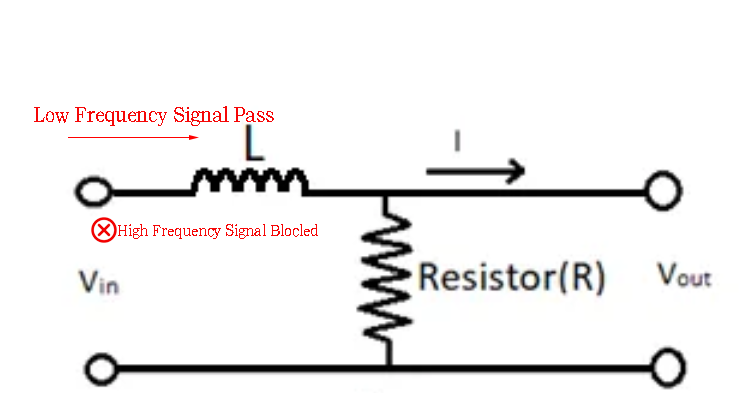 (Fig.8)
From the Fig.8 we can see that in RL low pass filter circuit, an inductor(L) and a resistor(R) connected in series, in this circuit, the inductor serves as the first component encountered by the input signal while the resistor acts as the second component but it is connected with the inductor in series.Below it is the reason why the inductor should be served as the first component encountered by the input signal:
From the equation , it becomes evident that as the frequency of the AC signal passing through the inductor increases, the resulting reactance also increases. At high frequencies, the inductor behaves like a large-value resistor that effectively impedes the signal from passing through. While it may not completely block the signal, its passage is significantly reduced compared to lower frequencies. On the other hand, at low frequencies, the inductor allows the signal to pass through. The cutoff frequency, represented by , signifies that AC signals above this frequency will be blocked, while signals below this frequency are permitted to pass.
If we interchange the positions of the inductor and resistor in the RL low-pass filter circuit, it becomes an RL high-pass filter circuit. Some beginner electronics enthusiasts may wonder why swapping the positions of the inductor and resistor in the RL low-pass filter circuit results in the opposite circuit structure. Now, let's explain the RL high-pass filter circuit to clarify why interchanging the positions of the inductor and resistor in the RL low-pass filter circuit leads to an RL high-pass filter circuit.
RL High Pass Filter Circuit
 (Fig.9)
From the Fig.9 we can see that in RL high pass filter circuit, the resistor acts like the first element encountered by the input signal while it is connected with the inductor in series configuration. As we know, for high frequency AC signal, the inductor has a high reactance that block the high frequency signal to flow through but allow low frequency to flow through, so, when signal composed of both of high and low frequency flow through the resistor, for the low frequency signal, the inductor as like a short-circuit component that let the low frequency signal pass it easily(filtered) while almost block or attenuate the high frequency signal(cutoff frequency) as it has a huge reactance to the high frequency signal, the high frequency signal has no other direction to go but only the direction of the Vout terminal on the above diagram, this is the reason why it is the RL high pass filter circuit, it filters the low frequency signal from the mixed signal before the signal goes to the Vout.
Power Consumption of an Inductor
As we know, when there is current flow through an inductor, the inductor will generate a self-induced emf voltage to oppose the change of the current, the power dissipated in an inductor is below:
(eq.1.7)
As
so (eq.1.8)
factor of 1/2 in the eq.1.8 representing the stored energy in an inductor arises from the nature of magnetic field energy. The energy stored in a magnetic field due to a current is not directly proportional to the square of the current. It's actually quadratic in current, but with a constant coefficient involved. Therefore, using 1/2 instead of 1 in the equation is a result of both the specific nature of magnetic field energy and the desire for mathematical convenience and consistency. It represents a standard convention in electromagnetism for expressing the stored energy in an inductor.
The Energy Stored in an Inductor
We learn from the above eq.1.8 that the power dissipated in an inductor is . According to the law of conservation of energy, the dissipated power is stored inside the inductor's magnetic field, so the energy stored in an inductor is given by:
so
Creative Commons tutorials are CC BY-SA 4.0 License