
Mondaykids Industrial Type Upgraded Version DKC-1A Stepper Motor Controller Pulse Generator Servo Potentiometer
$15.00
Availability:
In stock
SKU
BK-DG-20250409-01
Payment Security

We are PayPal Verified
PayPal is a secure and trusted payment processing service that allows you to shop online. PayPal can be used at mondaykids.com to purchase items by Credit Card (Visa, MasterCard, Discover, and American Express), Debit Card , or E-check (i.e. using your regular Bank Account).
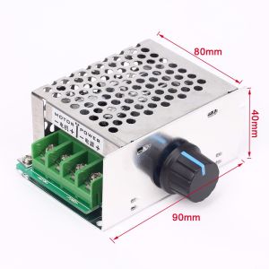
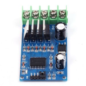
1. Product Introduction
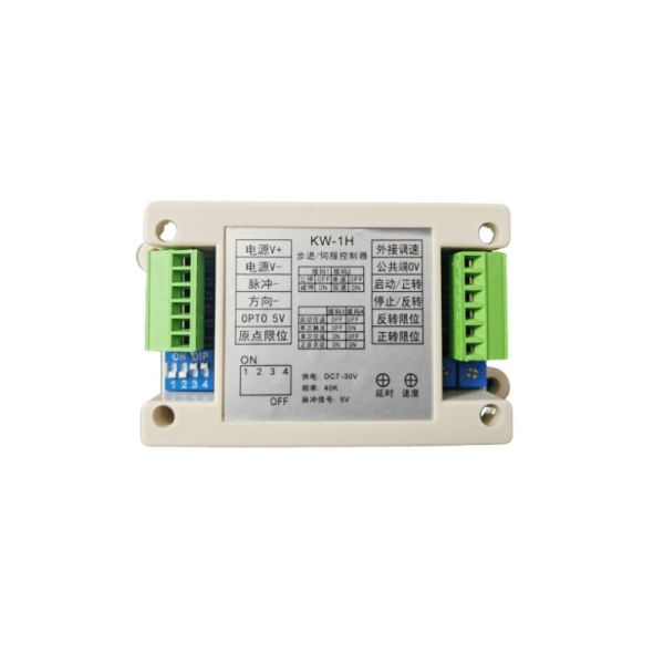
The KW-1H is an economical stepper motor controller with the following features:
- Wide input voltage: DC 7V–30V.
- Multiple protection functions: reverse polarity protection, overvoltage protection, and overcurrent protection.
- Motor speed control: supports both an onboard potentiometer and an external 5K potentiometer. A lower resistance yields a higher speed, while a higher resistance results in a slower speed.
- Input signals: active low.
- Output pulse frequency: up to 40KHz; common-anode 5V output delivers negative pulses.
- Positioning delay: adjustable from 0.2 to 6 seconds via the onboard potentiometer.
- Multiple operating modes: suitable for reciprocating motion, fixed-length control, speed control, etc.
- Plug-in terminal blocks: designed for convenient maintenance.
- Non-priority stop: a start command can immediately initiate motor operation even if a stop command was previously active.
2. Function Settings
2.1. Stop Mode Settings
| Stop Mode | Immediate Stop | Decelerated Stop |
| DIP Switch SW1 | OFF | ON |
2.2. Single/Double Speed Settings
| Speed Control Mode | Single-Speed Control | Dual-Speed Control |
| DIP Switch SW2 | OFF | ON |
3. Operation Mode Settings
| Mode | DIP Switch SW3 | DIP Switch SW4 |
| Automatic Reciprocal Mode | OFF | OFF |
| Single-Trigger Mode | OFF | ON |
| Single-Cycle Reciprocal Mode | ON | OFF |
| Forward/Reverse Jog Mode | ON | ON |
Note:
- Input signals are active low; the trigger signal must be maintained for at least 5ms.
- In single-speed mode, the system automatically switches between the onboard and external potentiometers.
- Except for Jog Mode, all other modes require a homing operation on first startup.
4. Wiring Instructions for Beginners
- Controller Power Supply: Connect a DC voltage of 12V or 24V, ensuring the correct polarity.
-
Pulse Signal Port Connections:
- Connect the controller’s 5V positive terminal to the driver’s pulse positive and direction positive terminals.
- Connect the controller’s pulse negative terminal to the driver’s pulse negative terminal.
- Connect the controller’s direction negative terminal to the driver’s direction negative terminal.
- Driver Power Supply: Connect according to the voltage requirement of the driver. A power supply with adequate capacity is recommended.
-
Motor Wiring:
- Two-Phase Stepper Motor: The four wires are divided into two pairs, which should be connected to the driver’s A+A– and B+B– terminals. If the rotation is reversed, swap the wires in group A.
- Three-Phase Stepper Motor: Connect the three wires to the driver’s U, V, and W terminals. If the rotation is reversed, swap the U and V wires.
-
Input Signal Settings:
- The start, stop, forward limit, reverse limit, and home limit are all input signals (active low).
- For proximity or photoelectric switches, use NPN normally-open types.
- For push-button switches, select self-returning normally-open types.
-
Potentiometer:
- Use a single-turn 5K potentiometer, connected between the controller’s common terminal and the speed control port. If the speed control direction is reversed, change the wiring configuration.
5. Debugging Methods
5.1. Driver Debugging
- Adjust the Current Setting: It is generally recommended to set the current to the minimum level that still provides adequate motor torque.
- Adjust the Microstepping Setting: Begin with 1600 or 3200 microsteps and adjust based on the required speed.
- Speed Calculation Formula: RPM = (Frequency ÷ Microstep Value) × 60.
5.2. Controller Debugging
- Switch to Jog Mode first to test the forward and reverse directions. If the directions are reversed, adjust the internal parameters accordingly.
- Beginners are advised to initially connect the controller, driver, motor, and power supply, using jumper wires to simulate switch functions. Once normal operation is confirmed, connect additional peripherals.
6. Functional Description
-
Automatic Reciprocal Mode:
- Upon starting, the motor rotates forward until it reaches the forward limit, then reverses direction upon hitting the reverse limit, and continues this cycle.
- If a stop command is applied, the motor halts. When the start command is triggered again, it resumes the previous direction.
- A delay of 0.2 to 6 seconds (adjustable via the onboard potentiometer) occurs upon reaching a limit.
-
Single-Trigger Mode:
- After the motor starts, it rotates forward and stops when reaching the forward limit. Triggering a start command again causes reverse rotation, stopping at the reverse limit.
- Each start command initiates rotation in the opposite direction from the previous cycle.
-
Single-Cycle Reciprocal Mode:
- The motor rotates forward upon start, then reverses upon hitting the forward limit and stops once the reverse limit is reached.
- A subsequent start command repeats the reciprocal cycle once.
- A delay of 0.2 to 6 seconds is applied after stopping at the forward limit.
-
Forward/Reverse Jog Mode:
- An active start signal rotates the motor forward, while an active stop signal rotates it in reverse. If neither signal is active, the motor remains stopped.
- The motor also halts when a limit is reached; note that this mode does not include a homing function.
7. Home Position Settings
- Home Switch: Connect the home switch to the designated port. Upon startup, the motor will initially move in reverse and then forward to locate the home position, stopping once it is found.
- Shorting the Home and Reverse Limit Terminals: By jumpering the home limit with the reverse limit terminal, the motor will interpret the reverse limit as the home position when starting up.
Write Your Own Review
Discover More Products from Its Parent Categories: